

In a prior article, I wrote about the principles behind designing record-breaking running robots. As I wrote then, one of the most helpful innovations over commercial humanoids appeared to be thermal:
What should we conclude from Honor’s accomplishment? First, the capillary motor cooling solution, if mass manufacturable, is a genuine advance, and I suspect this running pace would not have been sustainable without it.
In this article, I wanted to back up my claim about its necessity.
It might sound boring, but many devices we see around us are ultimately performance-constrained by thermals. In computing, all energy used is converted to heat. In machines and in robotics, where robots do physical work, a fraction of the input energy is converted to physical work, and the remainder is converted to heat. Heat results in higher temperatures, which ultimately causes failures in materials, mechanisms, and electronics. So, to increase your device’s performance, you need to understand heat transfer.
The TL;DR version of this article: using helpful analogies, I’ll describe how to arrive at two very simple principles to understand heat transfer: (a) establish the paths for heat flow, (b) study the bottlenecks in the shortest path before optimizing anywhere else. We will also see how to apply these principles to 3 very different applications: running robots, AI chips, and space datacenters.
Three methods of heat transfer → one coefficient
Heat transfer at first seems quite complicated. There are three primary mechanisms by which it can occur:
Conduction: Primarily in solids, molecules literally pass kinetic energy along to neighbors in direct physical contact
Convection: Fluids “carry” the heat by moving it along its flow
Radiation: Happens through electromagnetic waves, without any matter needing to move (or even be present)
These are distinctly different mechanisms, but there are a few very important similarities. For all of these, the energy transfered Q is proportional to both the temperature gradient ΔT and the area A of contact / exposure. In equation form,
where h, the heat transfer coefficient, is often nearly constant over a range of operating conditions.
This is an amazing fact! If you characterize or learn h somehow, you can model the relationship between the heat an object produces and what its temperature will be.
The problem is that a value of h will only be valid for a particular configuration of materials and environment. For example, if your device has a vertical exterior wall in still air, you can expect h ≈ 4.2 W/m2K (Watts, meters, and Kelvins appear in those units). But what if the exterior wall is made up of an exterior metal shell over an insulating plastic layer? What if there are vibration dampening grommets? Screws? Electronics? Any real device will be constructed of many materials and interfaces. How do we apply the equation above?
The circuit / flow analogy
Let’s think of the flow of heat as being represented by the flow of water through pipes. “h” says something about the thickness of the pipe, and how much it resists the flow.
At this juncture, if you’ve ever taken a circuits class, some bells may be ringing — flow of water through pipes is also the analogy typically used to explain the flow of electrons through circuits.
The analogy suggests a method of handling the complexity of multiple materials and interfaces — a circuit of resistors1 in series and parallel! The thermal resistance quantity R has units of K/W. You start with h and multiply it by the effective area through which the transfer occurs. Here’s a simple example combining conduction and convection from the inside of a solid cylinder to the air outside:2
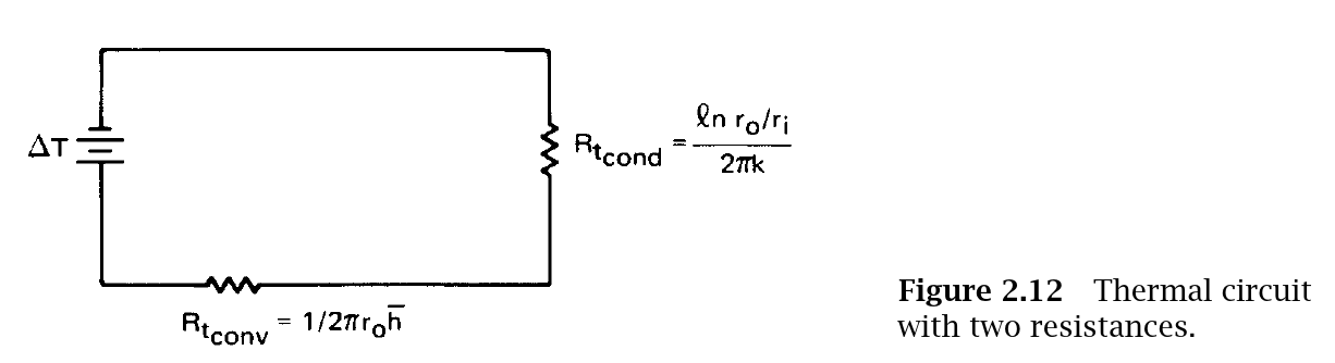
It is helpful to introduce an intermediate quantity called thermal conductivity k with units of W/(m.K), and combine with a characteristic length. If you look at datasheets of thermal paste or thermal pads for chips, they will be labeled with the k value. You simply multiply that with the thickness of the pad or paste layer and take the reciprocal to get resistance in K/W. In the pipe flow analogy, a pipe of a certain diameter has a fixed k value — the resistance is simply proportional to the length of the pipe segment.
These circuits can get very complicated, but finding the equivalent resistance is still a straightforward process.
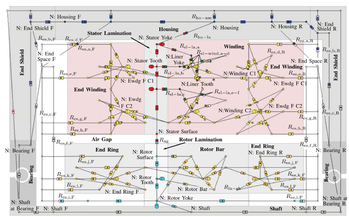
There are three important takeaways to remember:
You can use equivalent circuits to “build up” the value of R (in K/W) for complicated arrangements of materials.
Once you have R in K/W, you can multiply it with the power generated as heat (in Watts) to get the temperature rise (in Kelvin or Celsius).
The pipe flow analogy makes it clear that a narrow pipe, even when in series with a fat pipe, can be a bottleneck. In the simple series conduction-convection circuit above, if Rcond is high, there is very little that can be done with Rconv to improve the situation, since the equivalent is (Rcond + Rcond)!
Let’s apply these takeaways to the running humanoid robot.
Cooling a Robot Motor
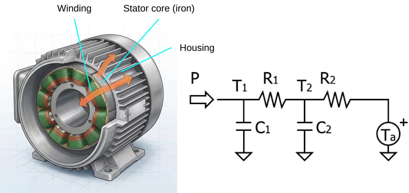
The main heat generating element in a motor is the copper winding through which current flows in order to generate a magnetic field. This heat must travel from the winding, through the stator core, and through the housing, outward. In many research papers (e.g. Urata 2008), this is lumped into a “mostly conduction” interior pathway from the windings to the housing, and a “mostly convection” exterior pathway from the housing to ambient:
In most robots, thermal management paths are to do with the latter (housing outward). This can include air cooling (potentially a fan near the housing) or a water cooling jacket:
With our principles from the previous section, let’s dig into the interior winding → housing pathway.
It’s unfortunately complicated. The copper itself needs electrically insulating enamel so that the windings don’t short, the coils go on separate stator teeth with gaps between them, and there is usually an interface between the stator iron and housing. The gaps between the teeth can be dry or potted with a thermally conductive but electrically insulating material.
Fortunately, there is a lot of research data on the equivalent conductivity keq of this layered system.
Following Sarma, we can relate the thermal resistance to an equivalent conductivity k and geometry of the motor

In our case study of the humanoid robot motor, we used an ILM115x25 motor, for which the inner and outer diameters are 86mm and 115mm and axial length La ≈ 50mm (choosing slightly longer than the stack length).
For the conductivity k, Sarma provides values for a spectrum of constructions, which result in the following range of thermal resistances:
Dry winding (no potting): keq = 0.1 W/m.K → Rcond ≈ 9 K/W
“Good” humanoid-joint motor: keq = 0.85 → Rcond ≈ 1 K/W
YASA axial flux: keq = 1.8 →Rcond ≈ 0.5 K/W
NASA HEMM potted Litz wire: keq = 3.5 →Rcond ≈ 0.26 K/W
Of these, the most applicable value is the second one, but let’s say we are optimistic and can make a thermally “really good” motor, and get the resistance down to 0.7 K/W.
Still, we have a problem!
As I showed in my prior article, the half-marathon running robot needs to dissipate 150 W continuously, and even the “really good” motor will increase its temperature by (at least) 105 C!
What if we continue our “really good” thermal engineering and put a fan on the outside of the motor for really low convection resistance Rconv? Unfortunately, as the equivalent resistance (series) is never going to be smaller than Rcond, we cannot lower our motor temperature whatever exterior cooling we apply!
Is there any way out?
Honor’s solution: capillary liquid cooling
Let’s revisit what Honor did:
According to Honor, the liquid - cooling pipes penetrate deep into the motors like capillaries. The high - power liquid pump has a heat - exchange flow rate of more than 4 liters per minute. Each of the four drive motors in the lower limbs is equipped with an independent liquid - cooling circuit.
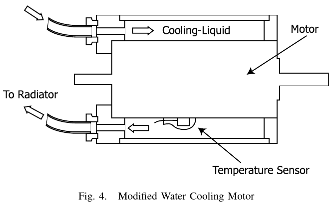
There is no public information on the detailed construction, but here is an image of a similar idea from a research paper:
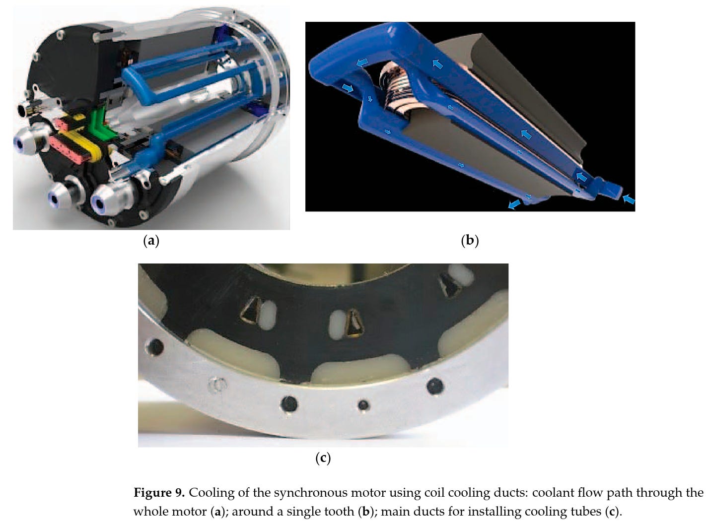
The key here is the breakdown of the internal conduction path.
The capillaries use liquid (which has significantly higher convective heat transfer capability than a gas)
The capillaries get much closer to the coils themselves
The exterior convection can take place across a much larger radiator area (instead of being limited to the area of the motor housing)
Here’s a rough numerical analysis of how this works.
Assume Honor runs N capillaries of 1 mm diameter through a motor. At 4 L/min total flow and 4 independent circuits, each leg gets 1 L/min flow. So the
Liquid velocity in each capillary: v = FlowRate / (N CrossSection) ~= 2 m/s
Table 1.1 in AHTT lists a few similar scenarios, say hcap ~ 3500 W/m2K conservatively
For 10 capillaries of 50 mm length, the total wetted area inside the stator is Acap = N π D L ≈ 0.0015 m2
So the thermal resistance is R = 1 / (hcap Acap) = 0.19 K/W
This baseline is significantly improved from the conventional scenario above!
Let’s do a very brief exterior cooling Rconv estimation following Table 1.1 from the Heat Transfer Textbook.
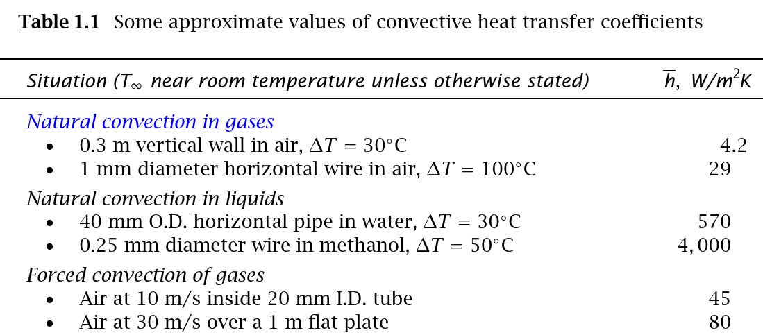
For a good fan, we’d get 50 W/m2K, and let’s say the radiator is a 30cm square, i.e. Aradiator = 0.09 m2, and so Rconv = 0.22 K/W.
In sum, with all this good engineering, we’re down to a total of 0.41 K/W. On top of this, radiation will also help slightly, reducing this value further.
Now, with a 150 W generated in the knee motor, we’re looking at a much more reasonable 60 C temperature rise.
Thermals never seem like a fundamental constraint of physics, like force or power limits, but they are just as real!
As noted in the numbered list above, the capillaries allowed us to (a) get closer to the heat source, and (b) decouple the convection area from the motor geometry itself.
Without (a), the heat would be bottlenecked inside the motor, and without (b), it would be bottlenecked getting discharged from the housing.
These two general principles are applicable much more broadly.
Chips and Space Datacenters
Computer chips can consume hundreds of Watts, but unlike motors, they do no physical work. All of those Watts need to be dissipated as heat.
Fortunately, unlike a motor, the physical size of the chip is small (shorter thermal pathway) and there are fewer different types of materials and thermal interfaces inside the chip.
Conventional chip cooling has utilized a short interior thermal path: Rcond encompasses the path from the transistors to the Integrated Heat Spreader (IHS), or directly to the top of the die. The rest of the path (which we lumped into Rconv) can involve heat pipes and a radiator, or a liquid cooling loop.
As with our motor example, as you can imagine, whatever you do with Rconv, you are limited by how good Rcond can be. This is referred to as the “thermal wall” and there is ongoing R&D into effectively integrating capillaries just like the motor:
TSMC’s Direct-to-Silicon Liquid Cooling redefines this paradigm by embedding microfluidic channels directly into the silicon structure, bypassing TIMs for near-zero thermal impedance. At the heart of this technology is the Si-Integrated Micro Cooler, a silicon-based solution fusion-bonded to the chip’s backside.
There has been a lot written about putting data centers in space, but to understand the cooling challenge you just need to again apply the same two principles. Even if you do incredible thermal engineering inside the space datacenter (reducing Rcond), you are stuck with the fact that the exterior cooling via Rconv is dismal because there nothing but vacuum around. Radiation is the only method of actually dispensing this heat, and becomes the bottleneck.
Final thoughts
Because of the laws of thermodynamics, almost anything you do will generate heat. And if this heat cannot be dissipated, temperature-related failures kill your product.
Fortunately, a couple of relatively simple intuitive principles guide this effect, and understanding them will help you spend your time and effort judiciously. Honor figured this out for their record-breaking humanoid robot, and developed the correct intervention to sustain high-speed running.
The other remedy is to not generate the heat in the first place, by reducing power consumption and increasing efficiency. Good thermal performance shouldn’t be an excuse for bad design! For more reading on this topic, I’ll link to some articles about power optimization in chip design and robotics below.
Thanks for reading! If you enjoyed this post, please like (❤️) and restack — it helps others find my writing. Subscribe to receive new posts.


It goes deeper — capacitor charging can also help represent the transient change in temperature over time. In this article we’re sticking to steady-state effects, i.e. the capacitors are fully charged and can effectively be removed.
The source of this image, and much of the introductory content is the free Heat Transfer Textbook which I would highly recommend.
Great article, Avik. Though, I am curious how much mass and volume this cooling system adds to the robot. So you have a choice of using that additional mass + volume budget on cooling or just making the motors slightly larger, which will not only increase their maximum torque/power output but also their surface area and thus cooling ability. Obviously this is probably not sufficient to run a marathon, but there's clearly a tradeoff there, with an inflection point at some duty cycle. The added complexity, cost, and liability of the cooling system is also a sore point.
Relatedly, it would be fun to figure out just how comically large the motors would need to be to run a marathon without liquid cooling or an ice pack. And at that point, how much higher can the robot jump?
Hello, my name is Hosein Aslami. I’m a graphic designer, and I’m very passionate about graphic design and creative work. Would it be possible for me to work with you? I would be happy to show you my skills and experience through a project. Thank you for considering me.